Common information
I created this induction heater based on this schematic from http://www.rmcybernetics.com:

BOM
One of the most important things would be the BOM I used. On the internet you’ll find a lot of suggestions. Due to the fact, that I want to use this heater as an induction furnace, I modified some parts so that the whole system can handle more power.
- R1, R2: 220R, 5W (yes, a little bit overpowered)
- D1, D2: UF4007
- T1, T2: IRFP260N
- C1: 1,98µF
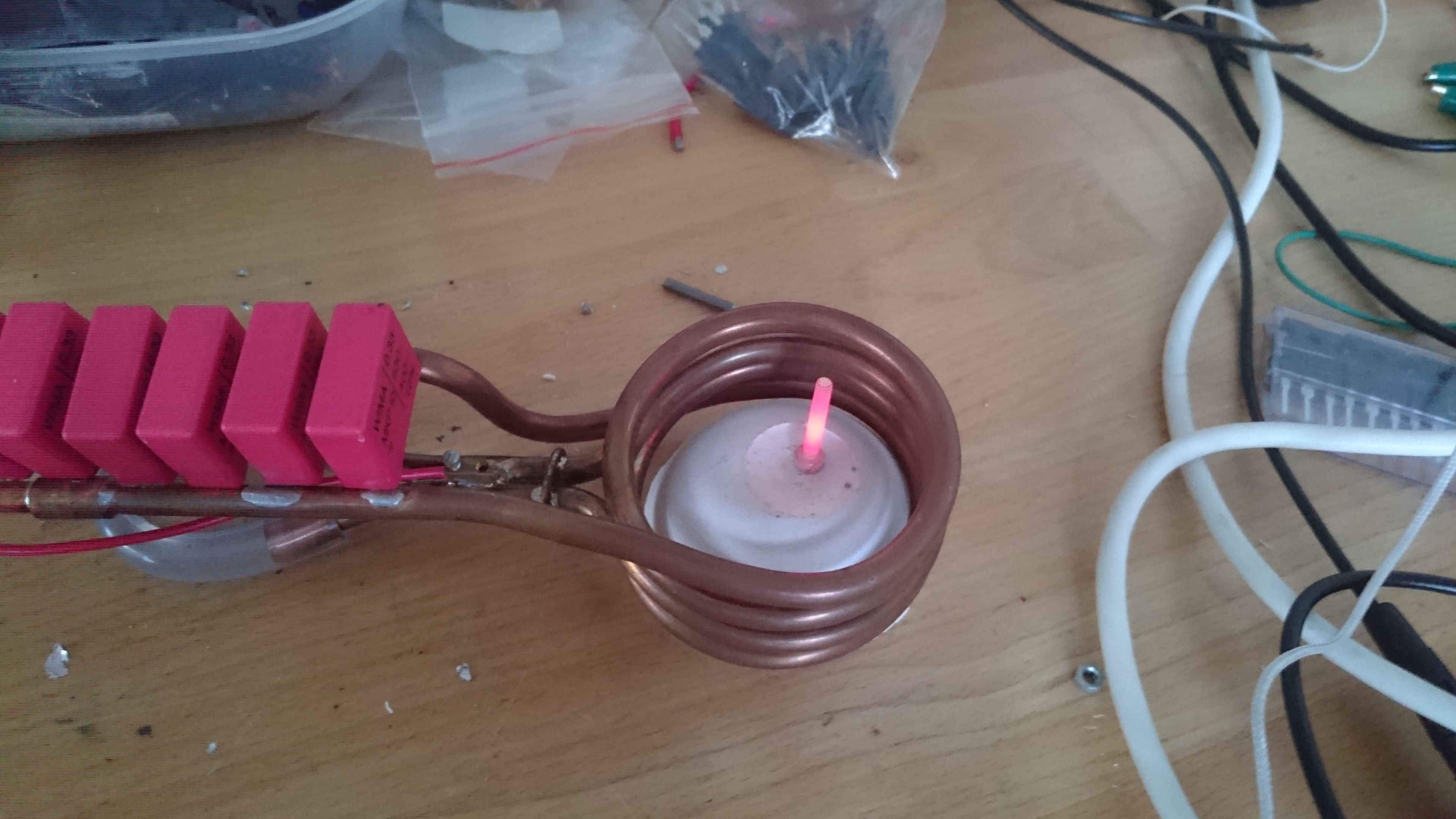
- 6 x WIMA MKP10 630V 0,33uF in parallel
- L1: as shown on http://www.rmcybernetics.com
- 6mm copper tubing with 60mm inner diameter – yes, we will need some active water cooling 🙂
- L2: 2mH
- 1,5mm magnet wire on a ferrite toroid (ø37x21x13,3mm).
Power supply
I have two 24VDC/12,5A SMPSs in parallel. These bring sufficient power for heating medium pieces of iron until they’re glowing. For an induction furnace I will need more power to heat my graphite crucible to at least 700°C for melting aluminum (melts at 660,4°C).
Evolution of construction
Here I offer you the chance to have a look at my progress of creation. I hope this helps you to avoid some unnecessary mistakes.
Back to the roots – wood and metal!
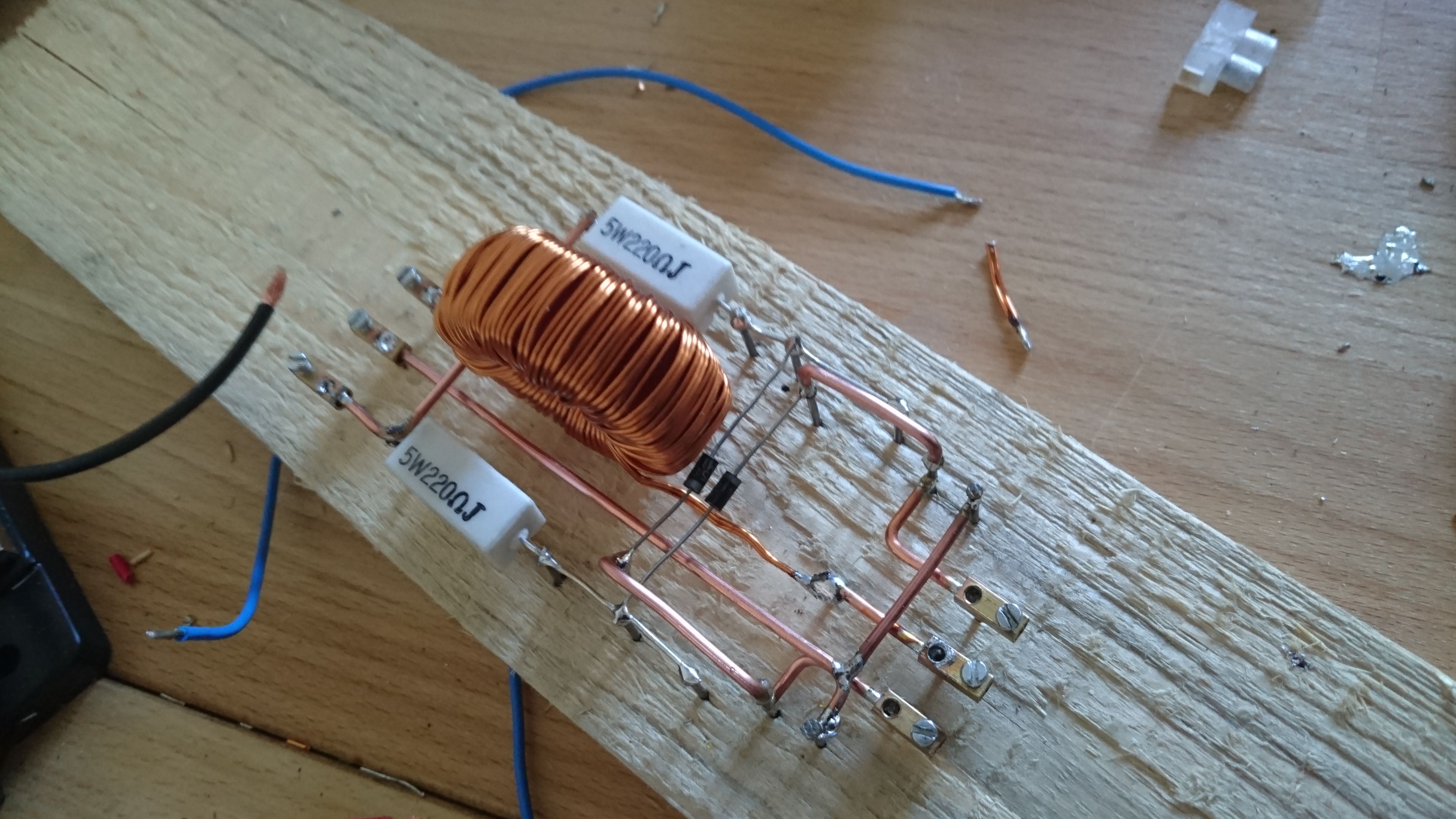
Because my breadboard went on fire I had to change my prototyping platform. Yes, beyond the driving circuit there is a lot of power!
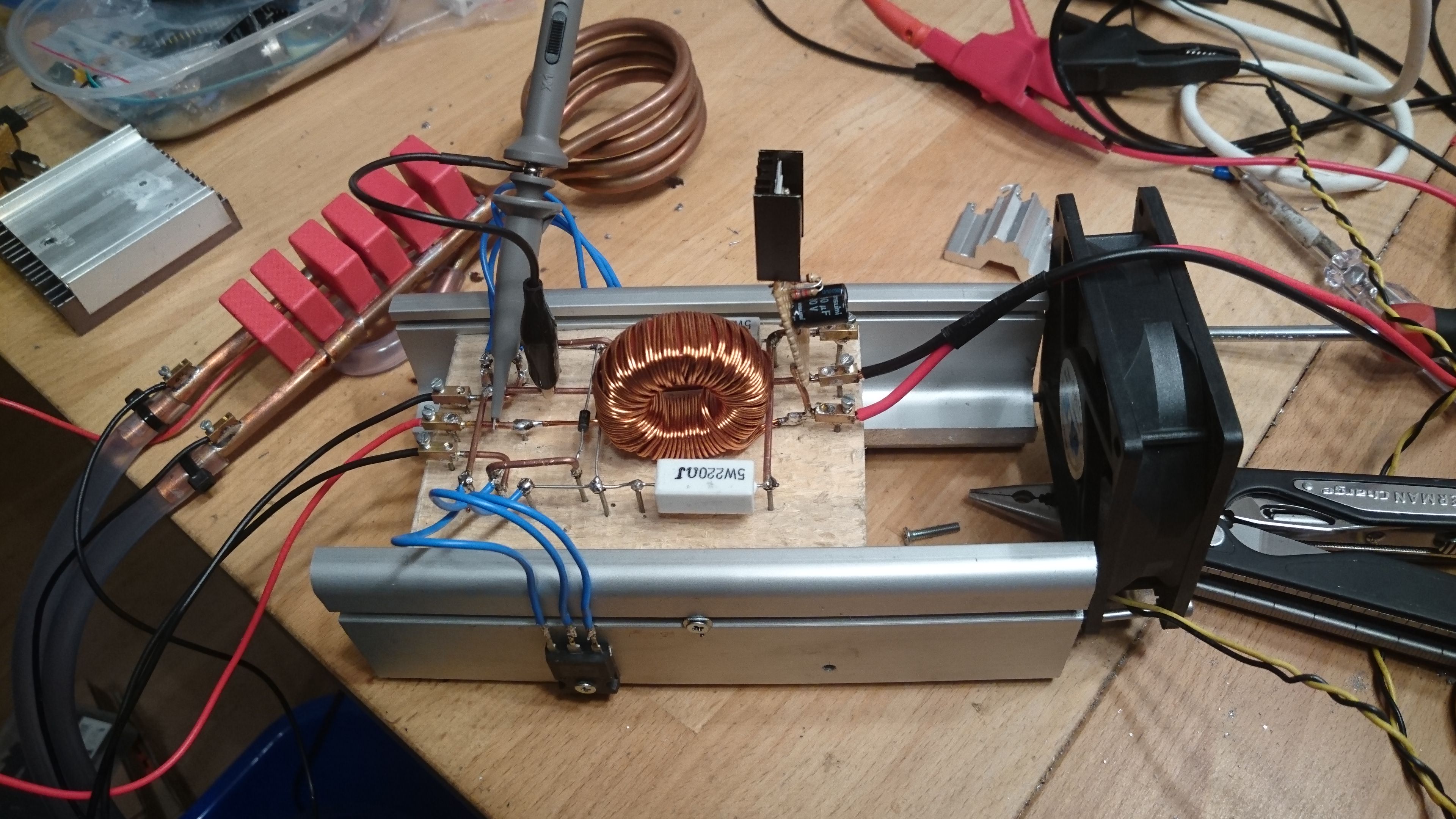
First (working) assembly
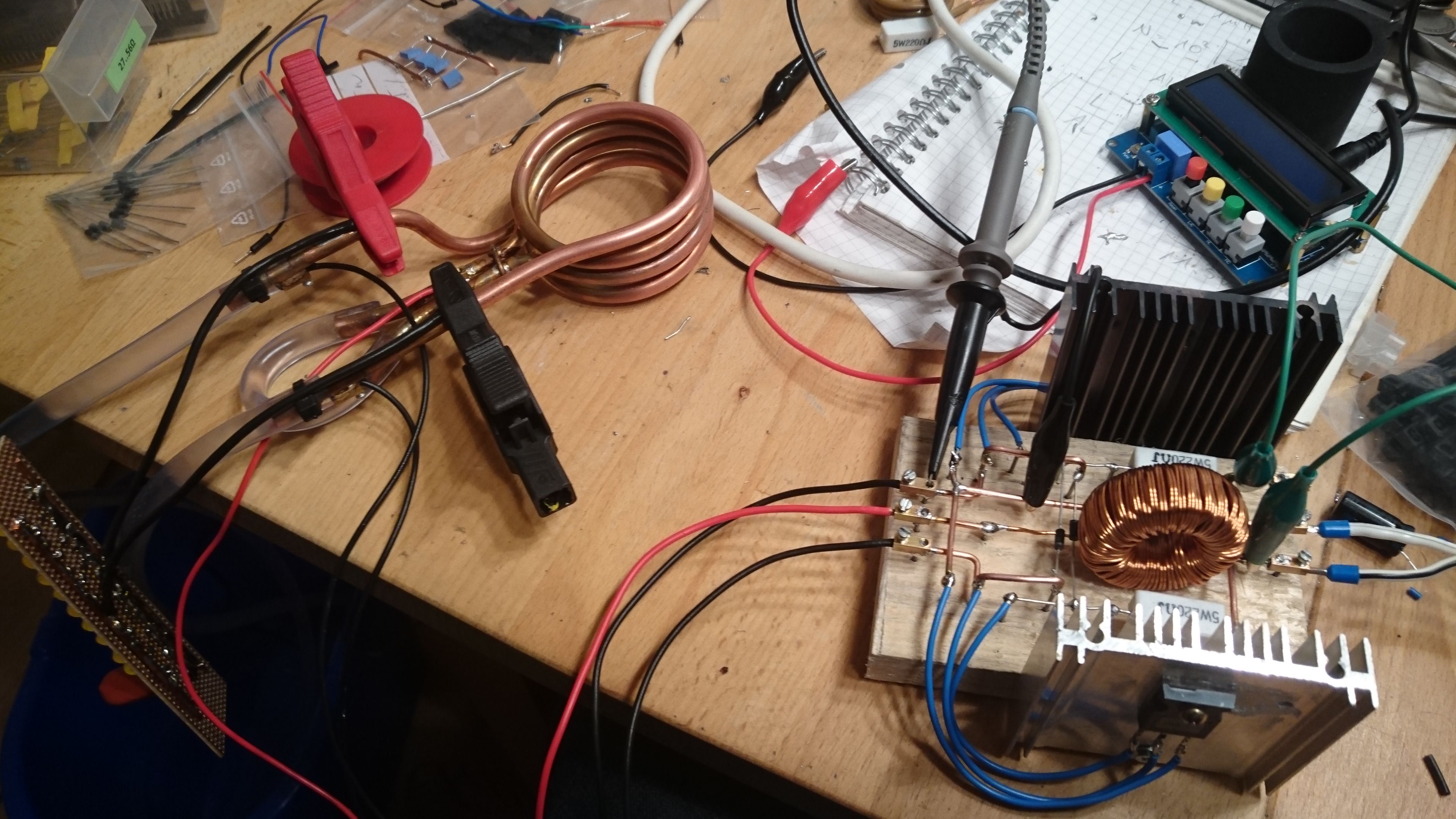
- water cooling
- circuit is working
- insufficient cooling of T1 and T2
- CAPs attached externally: a lot of heat on the wires and capacitors
But hey… its working! 😀
Next iteration
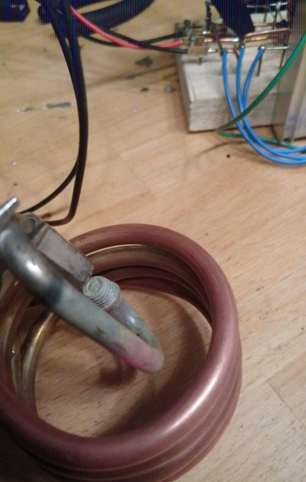
- CAPs now mounted on L1 directly:
- better power/heat transfer
- water cooling affects capacitor temperature as well
- T1, T2 cooling improved
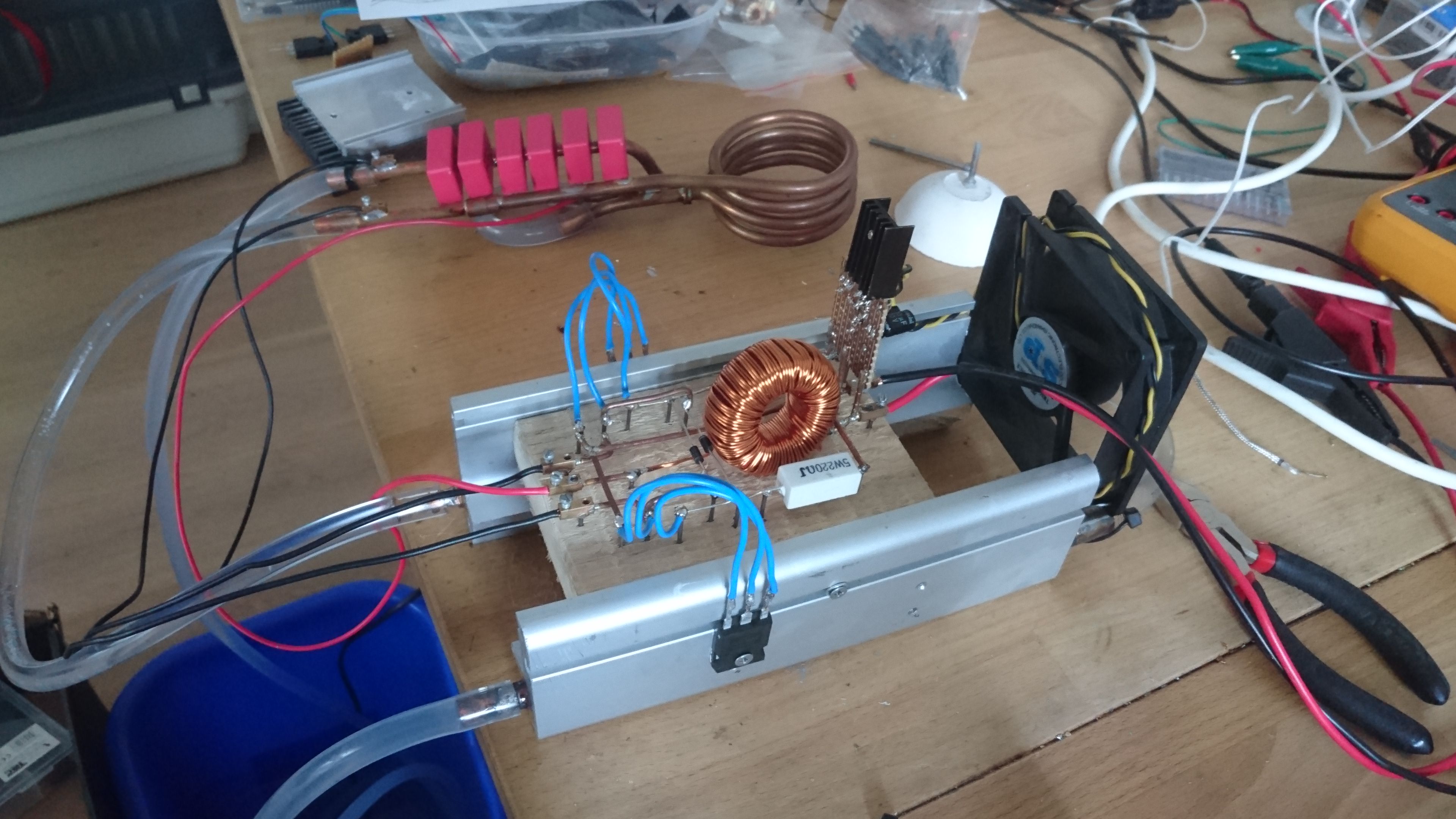
- bigger heatsinks
- active fan powered by a LM317 circuit at about 12VDC (when I recoil the choke this can be removed)
- T1, T2 cooling still not sufficient 🙁
Fun fact: This construction has a clever safety feature! If the FETs get too hot (yes, really hot), the attached drain wires snap off.
More cooling!
- T1, T2 heatsinks connected to existing water cooling. Fortunately these chunks of aluminum had a horizontal hole all the way through!
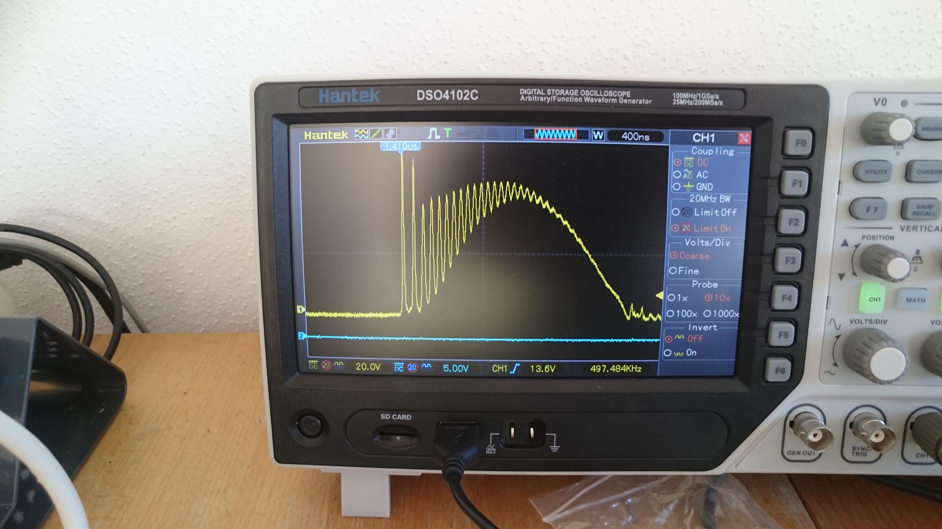
Some results
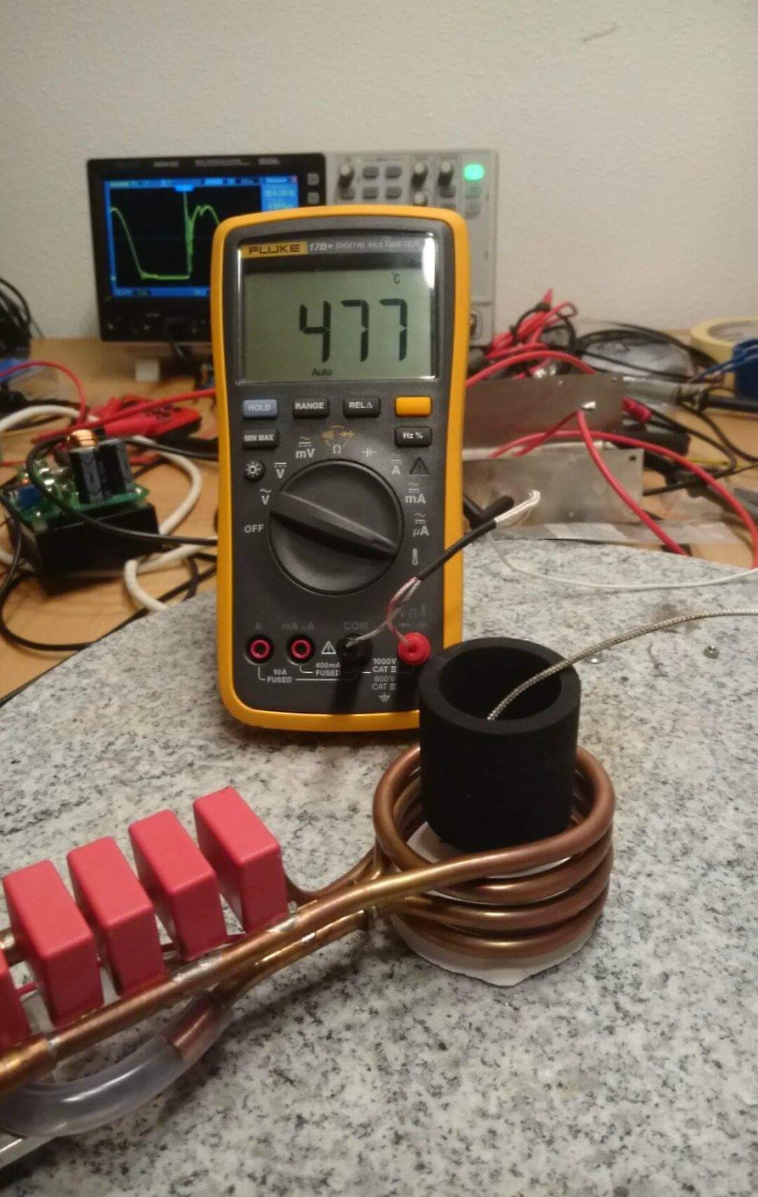
- I need at least 700°C!
- cooling is working perfectly
- need more power! 😀