Category Archives: Electronics

Skywatcher SynScan V4 Bluetooth Mod

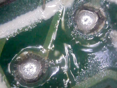
I saw a lot of similar mods for the older SynScan V3. Most of them connected the BT module to the serial port using an additional level shifter to convert levels back to TTL 3V3. Instead of using a second level shifter I did some research and determined the two TTL serial pins of the µC (pic18f85j10). Fortunately there were two vias next to those pins that could be used as tiny solder pads.

You need

  • Soldering iron with small tip
  • X-acto knife
  • A bluetooth module configured to 9600 baud
  • Thin magnet wire
  • Standard wires

Also very helpful:

  • A pair of good eyes
  • A calm hand
  • Patience

Overview

  • 5VDC can be drained from U9 (red=plus, black=minus)
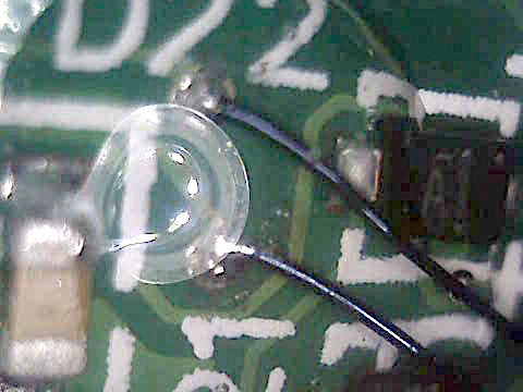
  • RXD (right, next to D22 print) -> connect to TXD on BT
  • TXD (left, next to D21 print) -> connect to RXD on BT

Fiddling

  1. CAREFULLY scratch away the solder mask coating.
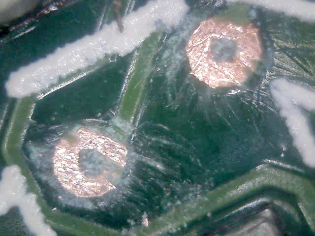
  2. Add some solder
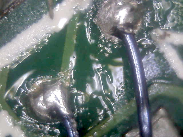
  3. Add thin magnet wire
  4. Use epoxy to secure the wires

To avoid the risk of ripping the magnet wires I soldered thicker ones onto them and secured their transitions with epoxy again (see entry image).

The BT module has some exposed pin headers that I used to connect the wiring to. To avoid any short circuits I put some heat shrink tubing around.

Setup successfully testet with SkySafari 5 Plus for Android.

That’s all Folks

Facebooktwitterredditpinterestlinkedinmail

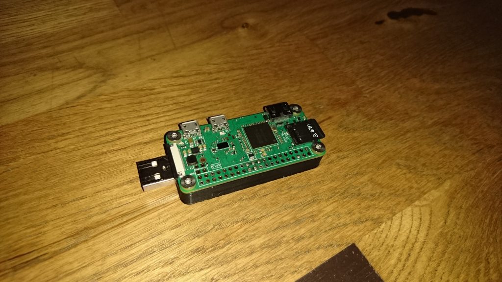
Unleash your Pi Zero W

Please note, that the USB power pads of a Pi Zero without WiFi will not match.

Ultimate

Lite

For the lite version you can skip all steps involving ENC28J60.

Hardware

  1. Raspberry Pi Zero /w (works for both)
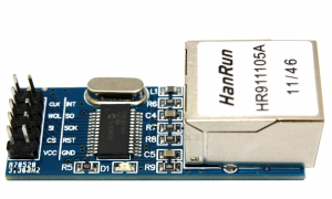
  2. ENC28J60 mini module (you have to desolder the pin header)
  3. An USB A plug (I ripped one from an old cable)
  4. Thin electric wires (old IDE cable works great)
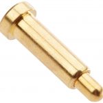
  5. 11 Pogo pins (L 9mm, D 2mm)
    Note: two of them need to be filed down for D+ and D-
  6. Some M2,5 screws

Housing

Download and print my 3D design:

Ultimate:
https://pinshape.com/items/39162-3d-printed-pi-zero-ultimate-housing

Lite (USB only):
https://pinshape.com/3d-printed-object/6321-pi-zero-lite-housing

Assemble

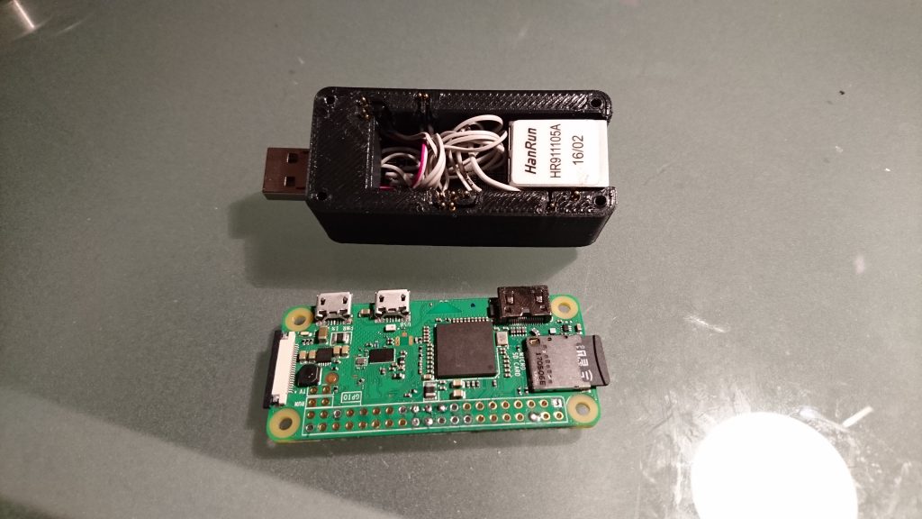
Solder the wires to the pogo pins and don’t forget to reduce the bottom diameter of two pins to fit into the holes for the USB data lines.

Yes, everything has a real tight fit!

USB connection

ENC28J60 connection

VCC(3.3V) -> 3V3    (Pin 1)
GND       -> GND    (Pin 6)
SI        -> MOSI   (Pin 19)
SO        -> MISO   (Pin 21)
INT/IRQ   -> GPIO25 (Pin 22)
SCK       -> SCKL   (Pin 23)
CS        -> CE0    (Pin 24)

To make good contact you should put some solder into the pin header holes of your PI’s SPI IOs and power supply.

Software (headless setup)

To have good performance, I used the Raspbian stretch lite: https://www.raspberrypi.org/downloads/raspbian/

After burning the image to a micro SD following files on the boot partition have to be adapted:

Add those two lines to the bottom of config.txt:

dtoverlay=dwc2
dtoverlay=enc28j60

Add this after rootwait to cmdline.txt:

modules-load=dwc2,g_ether

Enable SSH by placing an empty file named ssh to the boot partition.

Boot up and ssh into your pi zero:

ssh pi@raspberrypi.local

If you have a Windows machine, you need to install Bonjour to resolve the *.local suffix. Mac and Linux normally can handle this.

Final step

Enable SPI via raspi-config -> Interfacing Options

Reboot and enjoy real (but slow) Ethernet and Ethernet over USB!

Experiencing a boot loop? Try it again with an additional micro USB cable. It seems your computer doesn’t provide enough current.


Facebooktwitterredditpinterestlinkedinmail

Induction Heater

IMG-20160823-WA0004

Common information

I created this induction heater based on this schematic from http://www.rmcybernetics.com:

induction-heater-schematic

BOM

One of the most important things would be the BOM I used. On the internet you’ll find a lot of suggestions. Due to the fact, that I want to use this heater as an induction furnace, I modified some parts so that the whole system can handle more power.

  • R1, R2: 220R, 5W (yes, a little bit overpowered)
  • D1, D2: UF4007
  • T1, T2: IRFP260N
  • C1: 1,98µF
    • 6 x WIMA  MKP10 630V 0,33uF in parallel
  • L1: as shown on http://www.rmcybernetics.com
    • 6mm copper tubing with 60mm inner diameter – yes, we will need some active water cooling 🙂
  • L2: 2mH
    • 1,5mm magnet wire on a ferrite toroid (ø37x21x13,3mm).

Power supply

I have two 24VDC/12,5A SMPSs in parallel. These bring sufficient power for heating medium pieces of iron until they’re glowing. For an induction furnace I will need more power to heat my graphite crucible to at least 700°C for melting aluminum (melts at 660,4°C).

Evolution of construction

Here I offer you the chance to have a look at my progress of creation. I hope this helps you to avoid some unnecessary mistakes.

Back to the roots – wood and metal!

IMG-20160811-WA0001

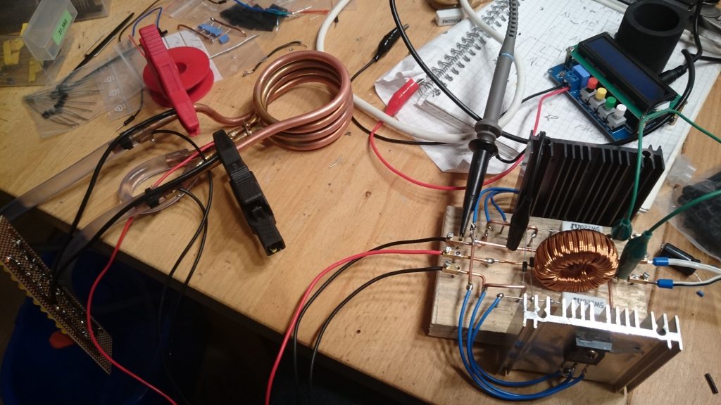
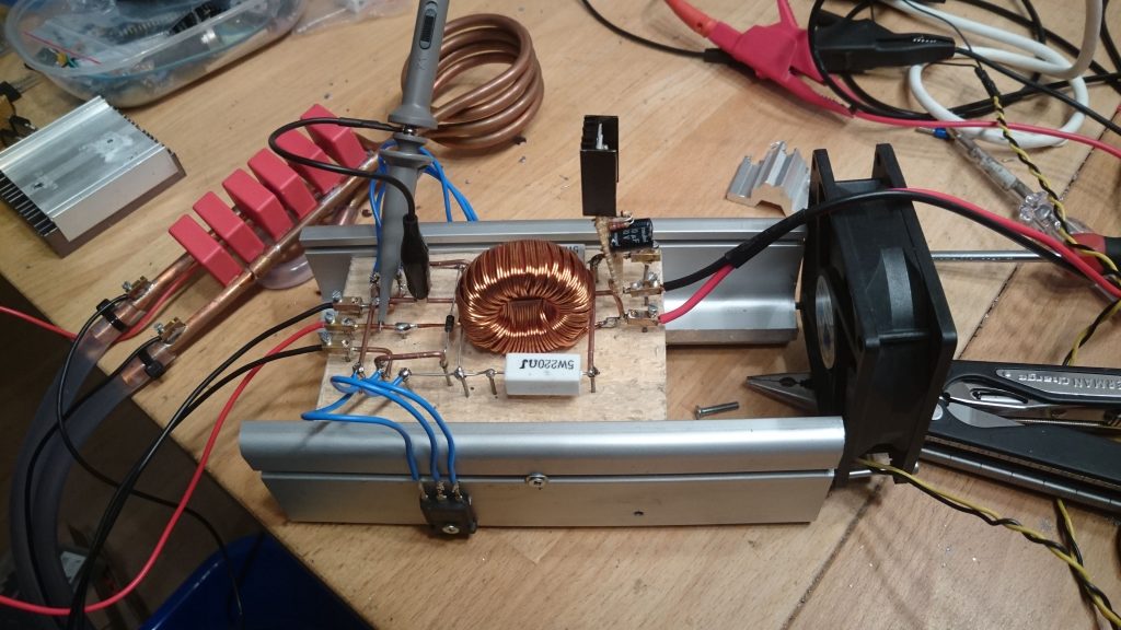
Because my breadboard went on fire I had to change my prototyping platform. Yes, beyond the driving circuit there is a lot of power!

First (working) assembly

IMG-20160811-WA0004

  • water cooling
  • circuit is working 
  • insufficient cooling of T1 and T2
  • CAPs attached externally: a lot of heat on the wires and capacitors

IMG-20160822-WA0004

But hey… its working! 😀

Next iteration

IMG-20160815-WA0002

  • CAPs now mounted on L1 directly:
    • better power/heat transfer
    • water cooling affects capacitor temperature as well
  • T1, T2 cooling improved
    • bigger heatsinks
    • active fan powered by a LM317 circuit at about 12VDC (when I recoil the choke this can be removed)
  • T1, T2 cooling still not sufficient 🙁

Fun fact: This construction has a clever safety feature! If the FETs get too hot (yes, really hot), the attached drain wires snap off. 

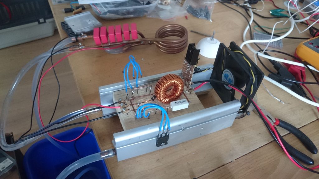
More cooling!

IMG-20160823-WA0002

  • T1, T2 heatsinks connected to existing water cooling. Fortunately these chunks of aluminum had a horizontal hole all the way through!

Some results

received_879516348849358

  • I need at least 700°C!
    • cooling is working perfectly
    • need more power! 😀

IMG-20160813-WA0005


Facebooktwitterredditpinterestlinkedinmail